Conceptual Design of Concrete Structures with FreeCAD and Paraview
Background
The FreeCAD FEM work bench has the capability of estimating the level of reinforcement required in a concrete structure to prevent brittle failure under tension or shear.
This is done with the method described in "Computation of reinforcement for solid concrete", P.C.J. Hoogenboom and A. de Boer, HERON Vol. 53 (2008) No. 4. In essence it is a post processing routine for Calculix, which calculates the principal tensile stresses in the concrete from an elastic analysis and uses those to determine the minimum reinforcement in the three coordinate directions required to prevent failure. In the analysis it is assumed that the concrete material cannot carry tensile stresses, whereas the steel is utilized to its maximum capacity (i.e. reaches yield).
The required reinforcement is expressed in terms of a reinforcement ratio. This is the ratio of steel to concrete area. For example a reinforcement ratio of 0.01 in x-direction (rx=0.01) means that the total cross sectional area of reinforcement bars running in x direction should be 1% of the concrete cross sectional area they are passing through. A hypothetical cross section of 1mx1m should in that case contain 0.01 m2 steel, which could be achieved by using 90 reinforcement bars of 12mm diameter each (steel area = 90*PI*(0.012)^2/4=0.0102 m^2). If the required reinforcement ratio over this concrete cross section is uniform then the bars could be placed at an equidistant 9x10 grid with a center-to-center distance of approximately 10cm. This is still a practical number where sufficient space between bars is left for the concrete to pass through and ensure a high quality cover. Much higher values would lead to a very dense reinforcement grid with potential quality issues, whereas much lower values could lead to large tension cracks in the cross section between the bars. A typical range in practice is from 0.002 to 0.02 (= 0.2% to 2%). Further guidance can be found in design codes.
If the required reinforcement ratio is not uniform over the full cross section then the cross section can be divided into pragmatic sub-sections with more or less uniform ratio and reinforcement applied to those cross-sections. An example will be given later on.
As a word of caution, it takes much more to design a safe and durable concrete structure than what the FEM work bench can currently provide. For example, the method does not calculate crack width (important for durability and functionality), accurate deformations (FEM results for concrete are simply linear-elastic) or take account of reinforcement anchoring requirements (causing an increase of required reinforcement ratios in anchoring zones). It also doesn’t predict concrete crushing (although an indication of that can be obtained by plotting the Mohr-Coulomb stress - see further), which could mean that the concrete fails before the reinforcement yields, causing brittle failure of the overall structure. These and other limitations mean that the FEM concrete functionality can only be used to assess conceptual designs, whereas detailed design decisions critical to safety and performance should be left to qualified professionals.
Model geometry, loads and supports
Although the FEM concrete routine does not have any additional requirements for geometry, loads and supports, it should be borne in mind that sharp corners and a support on an edge or vertex can introduce stress concentrations that will lead to extremely high and unrealistic reinforcement ratios at or near those locations.
Material Parameters
FEM workbench has a special material object for reinforced materials, which combines a matrix material (e.g. concrete) and a reinforcement material (e.g.steel). For the analysis of reinforced concrete with FEM, the following parameters need to be specified, as a minimum:
for concrete:
   - Young’s modulus (used in the Calculix analysis to calculate elastic deformations and stresses)
   - Poisson ratio (same)
   - uniaxial compressive strength (used during post-processing in FEM to calculate the Mohr Coulomb stress as an indicator for crushing or shear failure in concrete)
   - friction angle (same)
for steel:
- yield strength (used during post-processing in FEM to calculate reinforcement ratios)
Please note that three types of analysis are performed: 1) An elastic analysis using Calculix (only utilising the elastic parameters for concrete); 2) A post processing step to analyse the required reinforcement (only utilising the yield strength of steel) and 3) Calculation of the Mohr Coulomb stress (only using the strength parameters of concrete, i.e. uniaxial compressive strength and friction angle). The Mohr Coulomb stress can be reviewed in the VTK pipeline.
Application
In the remainder of this article a few practical cases will be analysed to discuss application of the method.
Simply supported beam with uniform load
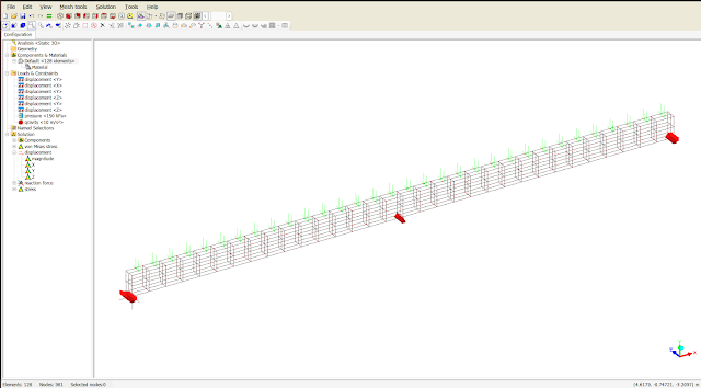
A 4.0x0.1x0.3m concrete beam is loaded by self weight and a 100kN (25kN/m) distributed load.
The material parameters are as follows:
for concrete:
   - Young’s modulus = 32 GPa (as per Calculix default for concrete)
   - Poisson ratio = 0.17 (as per Calculix default for concrete)
   - uniaxial compressive strength = 30 MPa (concrete type C30/37)
   - friction angle = 30 degrees
for steel:
- yield strength = 500 MPa
The specific weight of the concrete is taken as 24kN/m^3
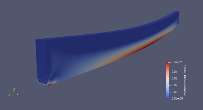
The required reinforcement in x-direction is very high (5.4%) and exceeds typical maximum percentages allowed by code to prevent brittle failure. The high shear stresses at the supports also lead to a requirement of high reinforcement:
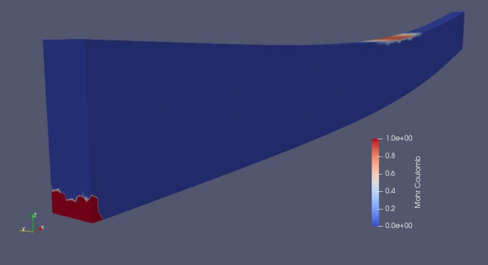
The Mohr Coulomb plot shows that beam is indeed prone to crushing on the
compression side (Mohr Coulomb stress > 0.0), as would be expected
with a very high reinforcement percentage:
Both the reinforcement ratio and Mohr Coulomb stress indicate that we have an issue and that we need to rethink our conceptual design. Potential solutions are to increase the beam dimensions or use pre-stressed concrete. Further details can be found in the following post: https://forum.freecadweb.org/viewtopic.php?f=18&t=28821&start=10#p235003
Beam with mid-span support
A 8.0x0.2x0.4m concrete beam is loaded by self weight and a 160kN (20kN/m) distributed load.
The material parameters are as follows:
for concrete:
   - Young’s modulus = 32 GPa (as per Calculix default for concrete)
   - Poisson ratio = 0.17 (as per Calculix default for concrete)
   - uniaxial compressive strength = 25 MPa (concrete type B25)
   - friction angle = 30 degrees
for steel:
- yield strength = 286 MPa (reduced from 500 MPa to account for a safety factor of 1.75)
The specific weight of the concrete is taken as 24 kN/m^3
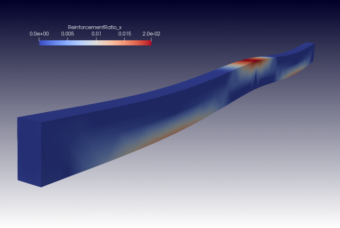
The ParaView plot of the exported VTK file shows that the reinforcement requirement is largest at the top of the beam near the central support. Here the highest bending moment occurs. The maximum reinforcement ratio is with 0.02 at the high end of the practical range quoted earlier:
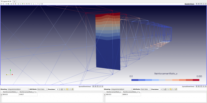
The required area of steel at the central support can be obtained with a ParaView integration filter applied to the mid section of the beam:
The panel at the bottom of this picture shows that the total required
steel area at this cross section is 389.6 mm^2. As one reinforcement bar
of diameter 12mm has a cross sectional area of 113mm^2, it means that 4
bars would be required, giving a cross sectional area of 452 mm^2.
These would need to be placed near the top of the beam, while
maintaining sufficient concrete cover. The theoretical center of gravity
for the reinforcement can be found by integration:
   CoG_y = Integrate (rx * y dy dz) / Integrate (rx dy dz)

   CoG_z = Integrate (rx * z dy dz) / Integrate (rx dy dz)
These integrals can also be determined with ParaView and give for the present case (see bottom panels in the above picture):
   CoG_y = 38961 / 389.6 = 100.0 mm

   CoG_z = 134917 / 389.6 = 346.3 mm
which is, as expected, center-width and near the top.
The reinforcement requirement found above agrees well with that obtained using traditional methods:
https://forum.freecadweb.org/viewtopic.php?f=18&t=28821&start=20#p235063
Finally, a Mohr Coulomb stress check should be performed to check potential crushing of the concrete. For this check, the characteristic compressive strength of concrete (25MPa) should be divided by an appropriate material factor (>1.0).
Shear wall with uniform load
A 4.0x2.0x0.15m wall is supported by two 0.5m wide columns. The wall is loaded by self weight and a 1.0MN distributed load at the top.
The material parameters are as follows:
for concrete:
   - Young’s modulus = 32 GPa (as per Calculix default for concrete)
   - Poisson ratio = 0.17 (as per Calculix default for concrete)
   - uniaxial compressive strength = 20 MPa
   - friction angle = 30 degrees
for steel:
- yield strength = 286 MPa
The specific weight of the concrete is taken as 24 kN/m^3
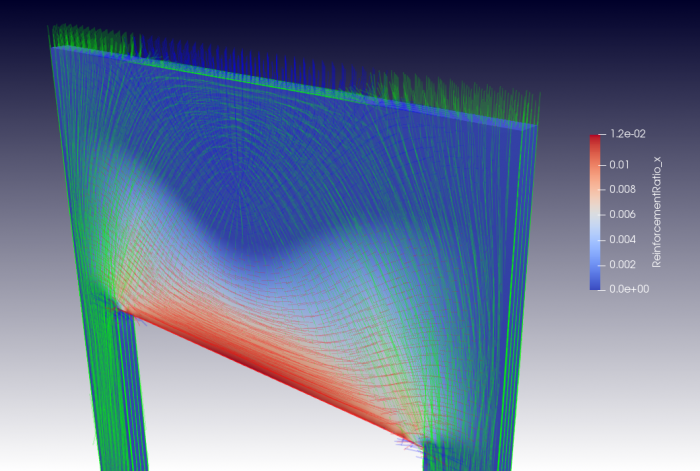
The horizontal reinforcement ratio peaks at 0.014 (1.4%) near the bottom center section of the wall and the vertical reinforcement ratio is at a maximum 0.008 (0.8%) near the corners of the wall with the columns, where the shear stresses are highest:
The above picture shows possible zones of constant reinforcement ratio for the design of reinforcement. Although a minimum reinforcement percentage of 0.2% is chosen, it will be hard to achieve such a low value in practice, given that the the spacing should not exceed a practical limit (say 300mm). Even with a light reinforcement grid of 10mm bars (cross sectional area = 78mm^2), the reinforcement ratio would then be 2 * 78 / (150 * 300) = 0.0035 (0.35%). (Note: the factor 2 stems from the fact that the grid will be placed at both faces of the wall). If we add one more bar to the grid (halving the distance) the reinforcement ratio would double to 0.7% and one more would give approximately 1%. So most of the reinforcement requirement could be achieved by starting off with a grid of d=10mm at 300x300mm spacing and adding bars in horizontal or vertical direction, as required. This would cover all but the requirement at the bottom of the wall, where we could add 3 bars d=12mm, giving a horizontal reinforcement ratio of 3 * 113mm^2 / (150mm * 150mm) = 0.015 (1.5%). Here it is assumed that the height of the bottom zone is 150mm. Alternatively, we could chose 2 bars of 16mm diamter, which would achieve the same reinforcement ratio for a zone of 180mm height.
Finally, a review of the Mohr-Coulomb stress shows that no concrete crushing is expected in the wall. https://forum.freecadweb.org/viewtopic.php?f=18&t=28821&start=10#p234673
Deep beam with opening
The FIB Practitioners' Guide to Finite Element Modelling of Reinforced Concrete Structures contains a design example of a deep concrete beam with opening. The example is used in that report to demonstrate the "Strut-and-Tie" method. Here the results will be compared to those obtained with the FreeCAD FEM workbench.
The beam dimensions are 11.0x4.0x0.6m and it is loaded at the top by a distributed load of 120kN/m and a load of 5000kN introduced by a 1m wide column. The factored compressive strength of the concrete is 0.75 x 0.6 x fc = 0.45 * 35 = 15.8MPa and the factored yield strength of the reinforcement steel is 315MPa.
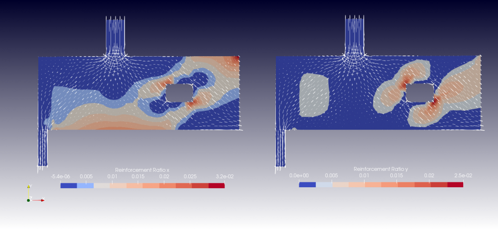
The reinforcement ratios and principal concrete stresses (compression only) derived with FreeCAD are shown below:
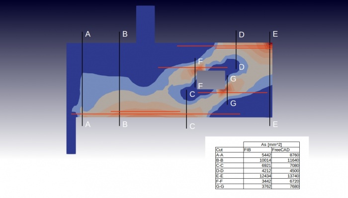
The required horizontal reinforcement (below in red) is determined by integration of the horizontal reinforcement ratio over the vertical cuts of interest (below in black). This is done using a Paraview integration filter.
The insert to the above figure shows a comparison of reinforcement requirements (in mm^2 of steel) determined with FreeCAD to those in the FIB report.
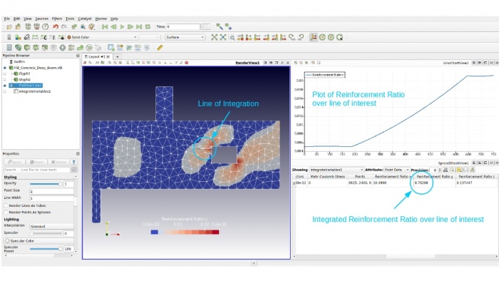
The following shows how the integration over lines of interest works in Paraview:
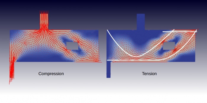
Finally a plot of compressive and tensile principal stresses to demonstrate how stresses flow through the beam.
The tensile stress pattern suggests an alternative design concept using pre-stressing cables (superimposed in white). This concept is further elaborated in the following post: https://forum.freecadweb.org/viewtopic.php?f=18&t=33049

.jpg)
Comments
Post a Comment